
Flexible Couplings
When transmitting torque from a drive shaft to a driven shaft, flexible couplings:
– Absorption and damping irregularities in the torque.
– Distribute peak loads.
– Allow misalignments and offsets between the shafts.
– Permit some distortions in the mounting beds.
– Avoid the unwelcome constraints that may occur if a rigid coupling were fitted in the same conditions.
– Allow a lighter construction, with wider tolerances, and lower cost.
– Moreover, there is no play and it therefore runs silently, without friction and does not need to be greased.
A flexible coupling is absolutely essential if the machines that are coupled are on flexible mountings.
Showing all 14 results
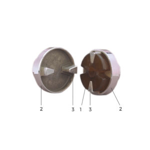
Flexible element:
1. Natural rubber block bonded to.
2. V-shaped metal armatures.
Flange: aluminium or cast-iron.
3. Drive segment.
Download PDF catalog
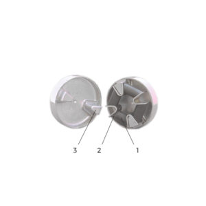
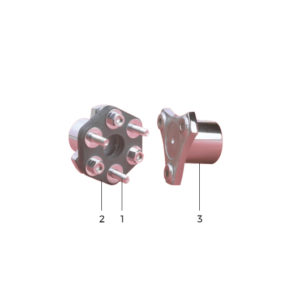
Flexible element 1: polyurethane in the form of a Maltese cross.
Flange 2: cast iron with drive segments 3 supplied unbored (except633054 and 633055).
Variations : For assemblies with a ring or spacer, consult our technical manuals.
Download PDF catalog
Flexible element:
1 Precompressed natural rubber
2 Bonded metal spacers,
3 Precompression band (to be removed after installation).
Flange:
4 Die-cast steel (except 632320 which is cast-iron).
Download PDF catalog
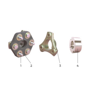
Flexible element:
1 Precompressed natural rubber.
2 Bonded metal spacers.
3 Precompression band (to be removed after installation).
Flange:
4 Die-cast steel specially bored to fit the separate hub.
5 Universal separate hub (not supplied by PAULSTRA).
Download PDF catalog

Flexible element:
1 Precompressed natural rubber.
2 Bonded metal reinforcing mountings.
3 Precompression band (to be removed after installation).
Flange:
4 Die-cast steel (except 632267 which is cast-iron).
Download PDF catalog
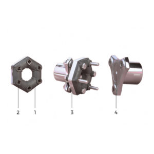
Flexible element:
1 Metallic bobbins linked together by rayon fibres.
2 The whole unit 1 is potted in natural rubber and is hexagonal.
Flange 3: forged steel.
Download PDF catalog
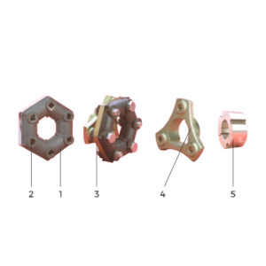
Flexible element:
1 Metallic bobbins linked together by rayon fibres.
2 The whole unit 1 is potted in natural rubber and is hexagonal.
Flange:
3 Forged steel specially bored to accommodate the separate hub.
4 Universal separate hub (not supplied by PAULSTRA).
Download PDF catalog
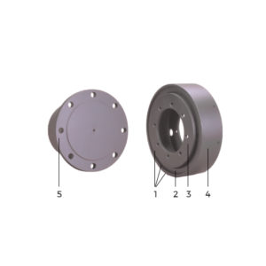
Flexible element 1 composed of:
2 Natural rubber ring.
3 Internal armature bonded to the rubber.
4 External collar force fitted to the rubber.
Flanges 5: die-cast steel fixed on to the internal armature 3 and collar 4.
Download PDF catalog
Flexible element:
1 Formed of solid natural rubber.
2 External steel surround, bonded to the rubber.
3 Triangular hub: a hollow hub bonded to the rubber and attached to the flange 5, or a solid hub which accommodates a grooved or keyed shaft.
Steel flanges:
4 round.
5 triangular.
Download PDF catalog
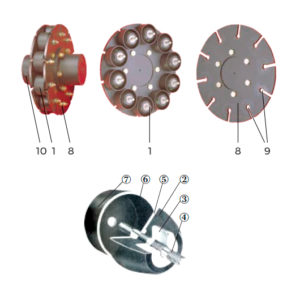
Flexible element made up of a variable number of FLEXIBLE STUDS
1 depending on the torque to be transmitted:
2 Solid natural rubber blocks in the form of a truncated cone.
3 Internal armature bonded to the rubber.
4 Threaded stud.
5 External armature bonded to the rubber.
6 Studding welded to armature.
7 Cylindrical metal cover.
Steel disks:
8 Two identical disks, bolted to the flanges 10 and with slits 9 to house the studs 1.
Flanges: 10 die-cast steel.
Download PDF catalog
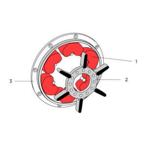
Flexible element:
1 Six fairly hard natural rubber shaped support blocks, on the inside edge of the outer ring of the coupling.
Flange:
2 inside flange has six arms which fit axially between the blocks by “blind axial” assembly.
Outer ring:
3 Ring with teeth that hold the blocks.
Standard SAE fixing and centring.
Download PDF catalog
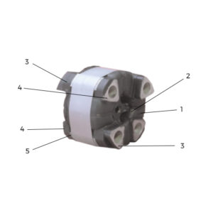
Flexible element comprising:
1 Natural rubber in the form of a cross.
2 A floating aluminium star, whose arms are bonded to the rubber.
Mountings:
3 Two aluminium bosses, bonded to the rubber, which will be attached to one of the machines.
4 Two aluminium bosses, bonded to the rubber, which will be attached to the other machine.
5 Band for precompressing the rubber before assembly.
Two retaining bars are supplied although not shown in the photo.
Download PDF catalog
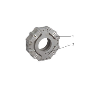
Flexible element comprising:
1 Natural rubber in the form of a cross.
2 A floating aluminium or steel star, whose arms are bonded to the rubber.
Mountings:
Two aluminium bosses, bonded to the rubber which will be attached to one of the machines.
Two bosses bonded to the rubber which will be attached to the other machine.
Download PDF catalog
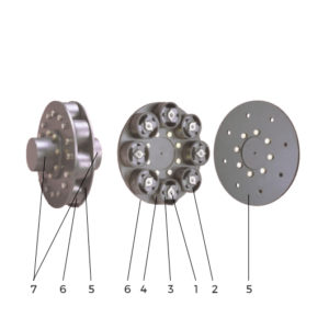
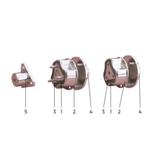
Flexible element comprising a variable number of flexible bushes, depending on the torque to be transmitted.
1 Inner with tapped or smooth holes (normal mounting or on fly wheel).
2 Precompressed natural rubber bonded to inner 1 and to outer the half-cylinders 3.
3 Half-cylinders bonded to the rubber.
4 Outer housing ensuring precompression of rubber by exerting pressure on the half-cylinders 3.
Steel disks:
5 Flange to which the inner studs are attached (normal mounting).
6 Disk to which the studs are attached (flywheel mounting).
Die cast steel hubs:
7 The two hubs are identical. They may be bolted to disks 5 or 6 depending on the mounting used.